| 4.1.6. |
Loads Due to Snow and Rain |
| 4.1.6.1. |
Specified Load Due to Rain or to Snow and Associated Rain
- The specified load on a roof or any other building surface subject to snow and associated rain shall be the snow load specified in Article 4.1.6.2., or the rain load specified in Article 4.1.6.4., whichever produces the more critical effect.
|
| 4.1.6.2. |
Specified Snow Load
(See Note A-4.1.6.2.)
- The specified load, S, due to snow and associated rain accumulation on a roof or any other building surface subject to snow accumulation shall be calculated using the formula

where
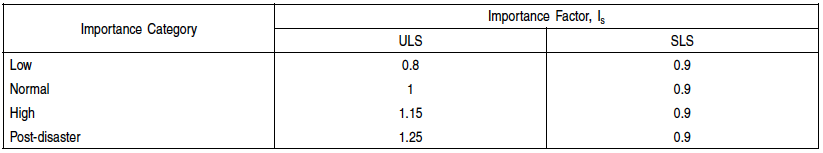
Is = importance factor for snow load as provided in Table 4.1.6.2.-A,
Ss = 1-in-50-year ground snow load, in kPa, determined in accordance with Subsection 1.1.3.,
Cb = basic roof snow load factor in Sentence (2),
Cw = wind exposure factor in Sentences (3) and (4),
Cs = slope factor in Sentences (5), (6) and (7),
Ca = accumulation factor in Sentence (8), and
Sr = 1-in-50-year associated rain load, in kPa, determined in accordance with Subsection 1.1.3., but not greater than Ss(CbCwCsCa).
Table 4.1.6.2.-A
Importance Factor for Snow Load, IS
Forming Part of Sentence 4.1.6.2.(1)
- The basic roof snow load factor, Cb, shall
- be determined as follows:

 where
where
lc = characteristic length of the upper or lower roof,
defined as 2w−w2/l, in m,
w = smaller plan dimension of the roof, in m, and
l = larger plan dimension of the roof, in m, or
- conform to Table 4.1.6.2.-B, using linear interpolation for intermediate values of lcC2w.
(See Note A-4.1.6.2.(2).)
- Except as provided for in Sentence (4), the wind exposure factor, Cw, shall be 1.0.
- For buildings in the Low and Normal Importance Categories as set out in Table 4.1.2.1., the wind exposure factor, Cw, given in Sentence (3) may be reduced to 0.75 for rural areas only, or to 0.5 for exposed areas north of the treeline, where
- the building is exposed on all sides to wind over open terrain as defined in Clause 4.1.7.3.(5)(a), and is expected to remain so during its life,
- the area of roof under consideration is exposed to the wind on all sides with no significant obstructions on the roof, such as parapet walls, within a distance of at least 10 times the difference between the height of the obstruction and CbCwSs/γ metres, where γ is the specific weight of snow on roofs as specified in Article 4.1.6.13., and
- the loading does not involve the accumulation of snow due to drifting from adjacent surfaces.
- Except as provided for in Sentences (6) and (7), the slope factor, Cs, shall be
- 1.0 where the roof slope, α, is equal to or less than 30°,
- (70° − α)/40° where α is greater than 30° but not greater than 70°, and
- 0 where α exceeds 70°.
Table 4.1.6.2.-B
Basic Roof Snow Load Factor for lc > (70/Cw2)
Forming Part of Sentence 4.1.6.2.(2)

- The slope factor, Cs, for unobstructed slippery roofs where snow and ice can slide completely off the roof shall be
- 1.0 where the roof slope, α, is equal to or less than 15°,
- (60° − α)/45° where α is greater than 15° but not greater than 60°, and
- 0 where α exceeds 60°.
- Unless otherwise stated in this Subsection, the slope factor, Cs, shall be 1.0 when used in conjunction with accumulation factors for increased snow loads.
- The accumulation factor, Ca, shall be 1.0, which corresponds to the uniform snow load case, except that where appropriate for the shape of the roof, it shall be assigned other values that account for
- increased non-uniform snow loads due to snow drifting onto a roof that is at a level lower than other parts of the same building or at a level lower than another building within 5 m of it horizontally, as prescribed in Articles 4.1.6.5., 4.1.6.6. and 4.1.6.8.,
- increased non-uniform snow loads on areas adjacent to roof projections, such as penthouses, large chimneys and equipment, as prescribed in Articles 4.1.6.7. and 4.1.6.8.,
- non-uniform snow loads on gable, arch or curved roofs and domes, as prescribed in Articles 4.1.6.9. and 4.1.6.10.,
- increased snow or ice loads due to snow sliding as prescribed in Article 4.1.6.11.,
- increased snow loads in roof valleys, as prescribed in Article 4.1.6.12., and
- increased snow or ice loads due to meltwater draining from adjacent building elements and roof projections.
- For shapes not addressed in Sentence (8), Ca corresponding to the non-uniform snow load case shall be established based on applicable field observations, special analyses including local climatic effects, appropriate model tests, or a combination of these methods.
|
| 4.1.6.3. |
Full and Partial Loading
- A roof or other building surface and its structural members subject to loads due to snow accumulation shall be designed for the specified load given in Sentence 4.1.6.2.(1), distributed over the entire loaded area.
- In addition to the distribution mentioned in Sentence (1), flat roofs and shed roofs, gable roofs of 15° slope or less, and arch or curved roofs shall be designed for the specified uniform snow load indicated in Sentence 4.1.6.2.(1), which shall be calculated using the accumulation factor Ca = 1.0, distributed on any one portion of the loaded area and half of this load on the remainder of the loaded area, in such a way as to produce the most critical effects on the member concerned. (See Note A-4.1.6.3.(2).)
|
| 4.1.6.4. |
Specified Rain Load
- Except as provided in Sentence (4), the specified load, S, due to the accumulation of rainwater on a surface whose position, shape and deflection under load make such an accumulation possible, is that resulting from the one-day rainfall determined in conformance with Subsection 1.1.3. and applied over the horizontal projection of the surface and all tributary surfaces. (See Note A-4.1.6.4.(1).)
- The provisions of Sentence (1) apply whether or not the surface is provided with a means of drainage, such as rainwater leaders.
- Except as provided in Sentence 4.1.6.2.(1), loads due to rain need not be considered to act simultaneously with loads due to snow. (See Note A-4.1.6.4.(3).)
- Where scuppers are provided and where the position, shape and deflection of the loaded surface make an accumulation of rainwater possible, the loads due to rain shall be the lesser of either the one-day rainfall determined in conformance with Subsection 1.1.3. or a depth of rainwater equal to 30 mm above the level of the scuppers, applied over the horizontal projection of the surface and tributary areas.
|
| 4.1.6.5. |
Multi-level Roofs
- The drifting load of snow on a roof adjacent to a higher roof shall be taken as trapezoidal, as shown in Figure 4.1.6.5.-A, and the accumulation factor, Ca, shall be determined as follows:

where
Ca0 = peak value of Ca at x = 0 determined in accordance with Sentences (3) and (4) and as shown in Figure 4.1.6.5.-B,
x = distance from roof step as shown in Figure 4.1.6.5.-A, and
xd = length of drift determined in accordance with Sentence (2) and as shown in Figure 4.1.6.5.-A.
- The length of the drift, xd, shall be calculated as follows:

where
γ = specific weight of snow as specified in Article 4.1.6.13.
Figure 4.1.6.5.-A
Snow load factors for lower level roofs
Forming Part of Sentences 4.1.6.5.(1) and (3) and 4.1.6.6.(1)

Notes to Figure 4.1.6.5.-A:
(1) If a > 5 m or h ≤ 0.8Ss/γ, drifting from the higher roof need not be considered.
(2) For lower roofs with parapets, CS = 1.0, otherwise it varies as a function of slope α as defined in Sentences 4.1.6.2.(5) and (6).
- The value of Ca0 for each of Cases I, II, and III shall be the lesser of
 where where
β = 1.0 for Case I, and 0.67 for Cases II and III,
h = difference in elevation between the lower roof surface and the top of the parapet on the upper roof as shown in Figure 4.1.6.5.-A, and  where where
Cws = value of Cw applicable to the source of drifting,
lcs = characteristic length of the source area for drifting, defined as  , where ws and ls are respectively the shorter and longer dimensions of the relevant source areas for snow drifting shown in Figure 4.1.6.5.-B for Cases I, II and III, and , where ws and ls are respectively the shorter and longer dimensions of the relevant source areas for snow drifting shown in Figure 4.1.6.5.-B for Cases I, II and III, and

where
hp = height of the roof perimeter parapet of the source area, to be taken as zero unless all the roof edges of the source area have parapets.
- The value of Ca0 shall be the highest of Cases I, II and III, considering the different roof source areas for drifting snow, as specified in Sentence (3) and Figure 4.1.6.5.-B.
Figure 4.1.6.5.-B
Snow load cases I, II and III for lower level roofs
Forming Part of Sentences 4.1.6.5.(1), (3) and (4)

|
| 4.1.6.6. |
Horizontal Gap between a Roof and a Higher Roof
- Where the roof of one building is separated by a distance, a, from an adjacent building with a higher roof as shown in Figure 4.1.6.5.-A, the influence of the adjacent building on the value of the accumulation factor, Ca, for the lower roof shall be determined as follows:
- if a > 5 m, the influence of the adjacent building on Ca for the lower roof can be ignored, and
- if a ≤ 5 m, Ca for the lower roof shall be calculated in accordance with Article 4.1.6.5. for values of x ≥ a.
|
| 4.1.6.7. |
Areas Adjacent to Roof Projections
- Except as provided in Sentences (2) and (3), the accumulation factor, Ca, for areas adjacent to roof-mounted vertical projections shall be calculated in accordance with Sentence 4.1.6.5.(1) using the following values for the peak accumulation factor, Ca0, and the drift length, xd:
- Ca0 shall be taken as the lesser of

- xd shall be taken as the lesser of 3.35h and (2/3)l0, where
h = height of the projection, and
l0 = longest horizontal dimension of the projection.
(See Note A-4.1.6.7.(1).)
- Ca is permitted to be calculated in accordance with Article 4.1.6.5. for larger projections. (See Note A-4.1.6.7.(2).)
- Where the longest horizontal dimension of the roof projection, l0, is less than 3 m, the drift surcharge adjacent to the projection need not be considered.
|
| 4.1.6.8. |
Snow Drift at Corners
- The drift loads on the lower level roof against the two faces of an outside corner of an upper level roof or roof obstruction shall be extended radially around the corner as shown in Figure 4.1.6.8.-A and may be taken as the least severe of the drift loads lying against the two faces of the corner.
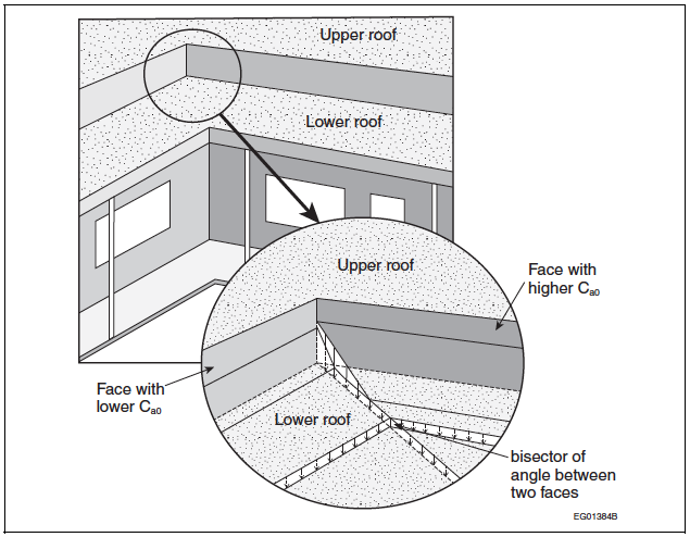
- The drift loads on the lower level roof against the two faces of an inside corner of an upper level roof or a parapet shall be calculated for each face and applied as far as the bisector of the corner angle as shown in Figure 4.1.6.8.-B.
Figure 4.1.6.8.-A
Snow load at outside corner
Forming Part of Sentence 4.1.6.8.(1)

Figure 4.1.6.8.-B
Snow load at inside corner
Forming Part of Sentence 4.1.6.8.(2)
 |
| 4.1.6.9. |
Gable Roofs
(See Note A-4.1.6.9.)
- For all gable roofs, the full and partial load cases defined in Article 4.1.6.3. shall be considered.
- For gable roofs with a slope α > 15°, the unbalanced load case shall also be considered by setting the values of the accumulation factor, Ca, as follows:
- on the upwind side of the roof peak, Ca shall be taken as 0, and
- on the downwind side of the roof peak, Ca shall be taken as
- 0.25 + α/20, where 15° ≤ α ≤ 20°, and
- 1.25, where 20° < α ≤ 90°.
- For all gable roofs, the slope factor, Cs, shall be as prescribed in Sentences 4.1.6.2.(5) and (6).
- For all gable roofs, the wind exposure factor, Cw, shall be
- as prescribed in Sentences 4.1.6.2.(3) and (4) for the full and partial load cases, and
- 1.0 for the unbalanced load case referred to in Sentence (2).
|
| 4.1.6.10. |
Arch Roofs, Curved Roofs and Domes
- For all arch roofs, curved roofs and domes, the full and partial load cases defined in Article 4.1.6.3. shall be considered.
- For arch roofs, curved roofs and domes with a rise-to-span ratio h/b > 0.05 (see Figure 4.1.6.10.-A), the load cases provided in Sentences (3) to (7) shall also be considered.
- For arch roofs with a slope at the edge αe ≤ 30° (see Figure 4.1.6.10.-A and Table 4.1.6.10.), Ca shall be
- taken as 0 on the upwind side of the peak, and
- on the downwind side of the peak, taken as

where
x = horizontal distance from the roof peak,
h = height of arch, and
b =width of arch.
Figure 4.1.6.10.-A
Accumulation factors for arch roofs and curved roofs
Forming Part of Sentences 4.1.6.10.(2) to (4)

Note to Figure 4.1.6.10.-A:
(1) Refer to Table 4.1.6.10. for applicable values of Cw and Sentences 4.1.6.2.(5) and (6) for applicable values of Cs.
- For arch roofs with a slope at the edge αe > 30° (see Figure 4.1.6.10.-A and Table 4.1.6.10.), Ca shall be
- taken as 0 on the upwind side of the peak, and
- on the downwind side of the peak,
- for the part of the roof between the peak and point where the slope α = 30°, taken as

where
x, h, b = as specified in Sentence (2), and
x30 = value of x where the slope α = 30°, and
- for the part of the roof where the slope α > 30°, taken as

- Except as provided in Sentence (6), Ca for curved roofs shall be determined in accordance with the requirements for arch roofs stated in Sentences (3) and (4).
Table 4.1.6.10.
Load Cases for Arch Roofs, Curved Roofs and Domes
Forming Part of Sentences 4.1.6.10.(3), (4) and (9)

- Where the slope, α, of a curved roof at its peak is greater than 10°, Ca shall be determined in accordance with the requirements for gable roofs stated in Article 4.1.6.9. using a slope equal to the mean slope of the curved roof.
- For domes of circular plan form (see Figure 4.1.6.10.-B), Ca shall
- along the central axis parallel to the wind, vary in the same way as for an arch roof with the same rise-to-span ratio, h/b, and
- off this axis, vary according to

where
Ca(x,y) = value of Ca at location (x,y),
Ca(x,0) = value of Ca on the central axis parallel to the wind,
x = distance along the central axis parallel to the wind,
y = horizontal coordinate normal to the x direction, and
r = radius of dome.
- For all arch roofs, curved roofs and domes, the slope factor, Cs, shall be as prescribed in Sentences 4.1.6.2.(5) and (6).
- For all arch roofs, curved roofs and domes, the wind exposure factor, Cw, shall be as prescribed in Table 4.1.6.10.
Figure 4.1.6.10.-B
Unbalanced snow accumulation factor on a circular dome
Forming Part of Sentence 4.1.6.10.(7)

Notes to Figure 4.1.6.10.-B:
(1) Refer to Table 4.1.6.10. for applicable values of Cw and Sentences 4.1.6.2.(5) and (6) for applicable values of Cs.
(2) Refer to Sentences 4.1.6.10.(3) and (4) for the calculation of Ca(x,0).
|
| 4.1.6.11. |
Snow Loads Due to Sliding
- Except as provided in Sentence (2), where an upper roof, or part thereof, slopes downwards with a slope α > 0 towards a lower roof, the snow load, S, on the lower roof, determined in accordance with Articles 4.1.6.2. and 4.1.6.5., shall be augmented in accordance with Sentence (3) to account for the additional load resulting from sliding snow.
- Sentence (1) need not apply where
- snow from the upper roof is prevented from sliding by a parapet or other effective means, or
- the upper roof is not considered slippery and has a slope of less than 20°.
- The total weight of additional snow resulting from sliding shall be taken as half the total weight of snow resulting from the uniform load case prescribed in Article 4.1.6.2. with
- the accumulation factor Ca = 1.0 for the relevant part of the upper roof,
- the slope factor, Cs, based on the slope of the lower roof, as prescribed in Sentences 4.1.6.2.(5) and (6), and
- the sliding snow distributed on the lower roof such that it is a maximum for x = 0 and decreases linearly to 0 at x = xd, as shown in Figure 4.1.6.11., where x and xd are as defined in Article 4.1.6.5.
Figure 4.1.6.11.
Snow distribution on lower roof with sloped upper roof
Forming Part of Sentence 4.1.6.11.(3)

|
| 4.1.6.12. |
Valleys in Curved or Sloped Roofs
- For valleys in curved or sloped roofs with a slope α > 10°, in addition to the full and partial load cases defined in Article 4.1.6.3., the non-uniform load cases II and III presented in Sentences (2) and (3) shall be considered to account for sliding, creeping and movement of meltwater.
- For case II (see Figure 4.1.6.12.), the accumulation factor, Ca, shall be calculated as follows:

where
x = horizontal distance from the bottom of the valley, and
b = twice the horizontal distance between the bottom of the valley and the peak of the roof surface in question.
- For case III (see Figure 4.1.6.12.), Ca shall be calculated as follows:

where
x, b = as specified in Sentence (2).
Figure 4.1.6.12.
Snow loads in valleys of sloped or curved roofs
Forming Part of Sentences 4.1.6.12.(2) and (3)

Notes to Figure 4.1.6.12.:
(1) CW = 1, as per Sentence 4.1.6.2.(3).
(2) CS = 1, as per Sentence 4.1.6.2.(7).
|
| 4.1.6.13. |
Specific Weight of Snow
- For the purposes of calculating snow loads in drifts, the specific weight of snow, γ, shall be taken as 4.0 kN/m3 or 0.43SS + 2.2 kN/m3, whichever is lesser.
|
| 4.1.6.14. |
Snow Removal
- Snow removal by mechanical, thermal, manual or other means shall not be used as a rationale to reduce design snow loads.
|
| 4.1.6.15. |
Ice Loading of Structures
- For lattice structures connected to the building, and other building components or appurtenances involving small width elements subject to significant ice accretion, the weight of ice accretion and the effective area presented to wind shall be as prescribed in CSA S37, "Antennas, Towers, and Antenna-Supporting Structures."
|