Condensation Resistance
Condensation can occur when moisture laden air comes in contact with a material with a surface temperature below the dewpoint temperature of the air. In a cold climate wall assembly, this usually occurs at the interior face (or back side) of the exterior sheathing when moisture from the conditioned space penetrates into the wall assembly through vapor diffusion or air movement. The addition of insulating sheathing to the exterior of an assembly in colder climates can provide for some condensation resistance within the wall assembly as it will change the thermal gradient through the assembly.
The thermal gradient across an assembly describes how the temperature varies from one side of an assembly through to the other. The thermal gradient can be predicted by examining the individual proportion of thermal resistance provided by each component. Each different component will provide a percentage of the total thermal resistance of the assembly. Therefore, the change in temperature of any component is based on the percentage of thermal resistance provided by that component multiplied by the overall temperature difference across the assembly.
∆T(comp) = R(comp) / R(total) x (T(in) - T(out))
Where:
∆T(comp) = temperature change across a component
R(comp) = thermal resistance of the component
R(total) = total thermal resistance of the assembly
T(in) = interior temperature
T(out) = exterior temperature
To determine the temperature at any given surface in the assembly, the individual temperature changes across each component in the assembly up to the desired surface is added to the exterior temperature.
T(surface) = T(out) + ∆T(comp 1) + ∆T(comp 2) + … + ∆T(comp n)
The example below examines the temperature of the inside surface of the exterior sheathing with an exterior temperature of 32F and an interior temperature of 70F. For the first section below, the temperature at the inside surface of the exterior sheathing would be calculated as:
T(surface) = T(out) + ∆T(exterior air film) + ∆T(plywood)
T(surface) = 32 + [0.17/20.92 x (68-32)] + [0.62/20.92 x (68-32)]
T(surface) = 32 + [0.0081 x 38] + [0.0296 x 38]
T(surface) = 32 + 0.31 + 1.13 T(surface) = 33.44 F
For the next two sections, the temperature of the inside surface of the exterior sheathing is 39.77 F and 44.74 F respectively.
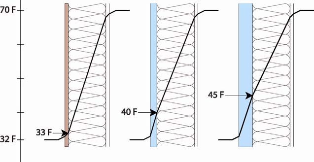
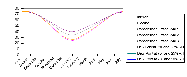
As it can be seen from the figure above, with the additional thermal resistance of the rigid board insulation material, the temperature of the inside face of the sheathing will be warmer in the winter months than with traditional wood sheathing alone. Since the surface temperature is warmer, there is less of a risk of condensation forming on the inside face. If the exterior wood sheathing eliminated, the system becomes even more durable as insulation sheathings are resistant to water and will not degrade if a small amount of condensation does occur.
For this to be applied effectively, understanding the climate zone and the interior environmental conditions in which the assembly is being designed is very important. As an example, three different wall sections were examined in three different locations. In each example the interior conditions were set at 70F and 35% Relative Humidity. Air under these conditions will have a dew point of approximately 40F (determined from the psychometric chart). Also, each assembly was assumed to have a vapor permeable interior finish or no effective interior air barrier layer allowing for the more humid interior air to come in contact with the interior face (condensing layer) of the exterior sheathing.
The three wall sections were analyzed for the Chicago, IL area with the exterior conditions based on the average monthly temperatures for a one year cycle. The first wall section, designed under the traditional approach with wood sheathing, is at risk of condensation accumulation on the back of the wood sheathing from the middle of November to the middle of March (this is shown by the segment of the temperature profile that drops below the dewpoint of 40F for the interior air). With the addition of 1 inch of insulating sheathing, the time period of condensation potential time is now from the middle of December to the middle of February. The addition of 2 inches of insulating sheathing the temperature profile does not drop below the dewpoint temperature, and therefore no longer at risk. With 2 inches of insulating sheathing, the wall assembly would not require an interior vapor control layer or interior continuous air seal.
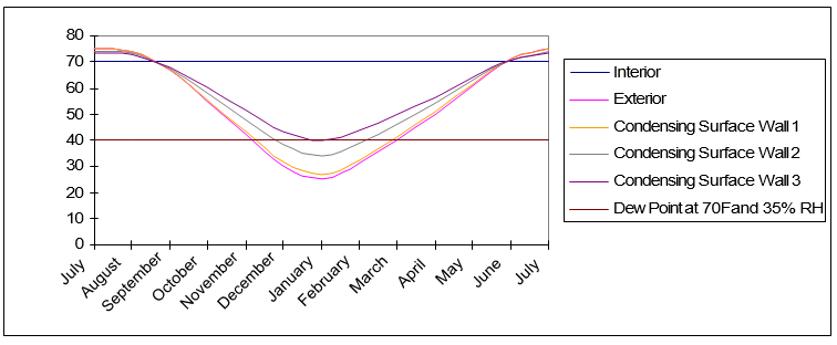
If the wall sections are moved to Minneapolis, MN exterior insulating is no longer adequate on it's own to manage the condensation resistance of the wall assembly. For each profile, an interior vapor control layer and air barrier would be required.
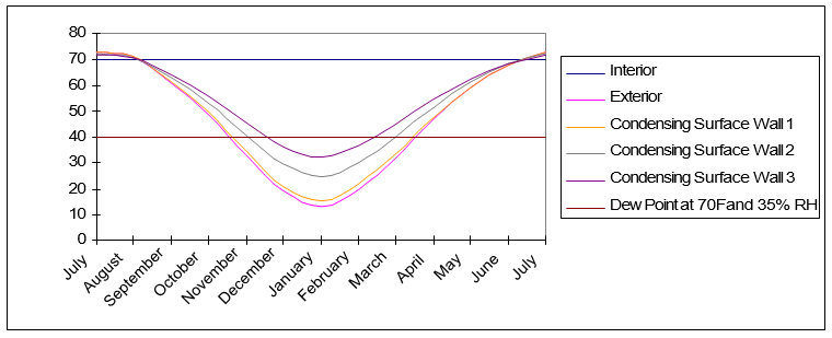
Conversely, if the profiles are moved to Seattle, WA, the exterior conditions are not cold enough to create problems with condensation even with the traditional approach (as long as the interior relative humidity is maintained below 35% RH).
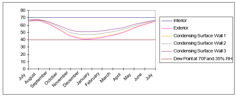
If the interior conditions change, the condensation potential will also change. Reexamining the Chicago, IL sections once again and varying the interior relative humidity demonstrates that 1 inch of insulating sheathing would be adequate if the relative humidity was kept below 25% (dewpoint of 32F ), or that 2 inches of insulating sheathing would not be adequate if the interior relative humidity increases to 50% (dewpoint of 50F).
While the use of insulating sheathing can help to reduce the condensation potential, it is only a component in the overall design of the building enclosure assembly. The examples above were used to demonstrate how insulating sheathing can reduce the condensation potential in an assembly; however, design of the building enclosure will likely include other water, air, and vapor management strategies as well.
As mentioned earlier, in mixed humid climates, the thermal gradient approach can be used as part of the vapor management strategy. The use of impermeable insulating sheathing materials of adequate thickness to ensure that the dewpoint temperature is not reached within the assembly, will allow for the interior vapor control layer to be eliminated from the assembly (installing a vapor retarder on the interior would actually be detrimental to the system).
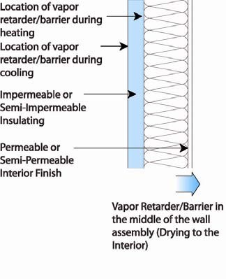
With the impermeable or semi-impermeable nature of the sheathing, the exterior face of the board would function as a vapor retarder during the cooling month, while the interior face of the insulating sheathing would function as a vapor retarder in the heating months. The air barrier for the system could also be installed to the interior or exterior of the assembly. This approach should also be combined with a slight positive interior pressure to limit the amount of infiltration of moist air during the cooling season as well as some interior moisture control to ensure that the interior RH does not exceed the maximum levels to prevent condensation on the interior surface of the exterior sheathing during the heating season.