Exterior Frame Wall
The most effective location for the enclosure control functions - water, air, vapor, and thermal -- for the exterior walls of a house is to the exterior of the existing structure. Some advantages to this approach for a DER include minimizing the impact of the wall retrofit on the interior finishes of the existing house, supporting continuity of the water and air control layers, reducing thermal bridges, and lowering the risk of water damage and condensation within the existing wall structure. This is the approach used for the DER exterior wall assembly in this guide.
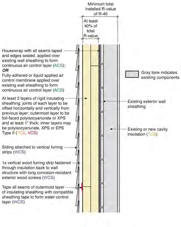
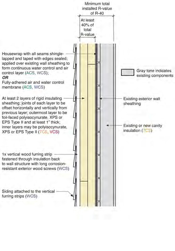
In the retrofit wall assembly, the air control layer is applied directly over the existing wall sheathing and then covered by at least two layers of insulating sheathing held in place by vertical furring strips. The vertical furring strips also provide the means of attachment for the exterior siding
In the drawings, the wall siding is represented as lap siding which could be wood, vinyl or fiber cement lap siding. Other types of siding that can be attached using the vertical furring strips may be used as well provided the weight of the siding is less than 10 lb/ft2
There are two possible locations for the water control layer for this retrofit wall assembly - at the outer face of the insulating sheathing or between the insulating sheathing and the existing exterior wall. The location of the water control layer has implications about how the water control function is handled at transitions and interruptions. For example, in window installation, if the water control layer is over the existing sheathing, the windows are installed within the existing wall framing whereas if the water control layer is at the face of the insulating sheathing, the windows are installed within the insulating sheathing layer of the wall. This is because the window flashing needs to be integrated into the water control layer.
In this guide, both locations of the water control layer are supported. Wall 1A is the retrofit wall assembly with the water control layer on the face of the insulating sheathing. Wall 1B is the retrofit wall assembly with the water control layer applied to the face of the existing wall sheathing. For Wall 1B, the water control layer is also the air control layer. Once the location of the water control layer for the wall has been established, it is essential that only compatible transition and interruption details be selected for use. For example, if Wall 1A is selected as the wall assembly for the DER project, only drawings, sequences, and details that are labeled either for Wall 1 or for Wall 1A should be used. Those that are labeled for use with Wall 1B are not compatible and should not be used.
The retrofit wall assembly calls for multiple layers of insulating sheathing to be applied to the exterior of the existing wall. This creates a vapor impermeable layer on the exterior of the wall. If there is a wetting event (e.g. a plumbing leak) that causes the existing wall structure to become wet, it is important that the wall is able to dry to the inside. For this reason, any new or existing application of closed cell spray foam in the wall cavities should be limited to a thickness of one inch. In general, any spray foam insulation applied to the wall cavity should have a vapor permeability of at least 1.0 perms for the installed thickness. Open cell spray foam insulation meets this criteria for typical framed wall cavity depths.
It is advisable to avoid use of an interior side vapor barrier and vapor impermeable wall coverings, including non-latex paint and some wallpapers, with this retrofit wall since these limit the drying potential to the interior as well. These types of wall coverings may contribute to problems if the interior space has high humidity, there is a history of water leakage in the wall, or the exterior wall has gotten wet during construction.

Wall 1A: Cavity Insulation and Insulating Sheathing with Water Control at Face of Insulating Sheathing
- No more than 1" of closed-cell spray foam insulation (new or existing) should be used in the wall cavity; for other types of spray foam insulation, the vapor permeance of the installed thickness must be at least 1.0 perm; this may not be the case for some medium density spray foams.
- This retrofit wall assembly is not advised for use on walls for which there is an existing interior side vapor barrier (including certain paints and wall paper) if the interior space has high humidity, there is a history of water leakage in the wall, or the wall has gotten wet during construction.
- Application of a continuous vapor impermeable wall covering, including certain paints and wall paper, should be avoided if the interior space has high humidity, there is a history of water leakage in the wall, or the wall has gotten wet during construction.

Wall 1B: Cavity Insulation and Insulating Sheathing with Water Control Between Sheathing and Insulating Sheathing
- The air and water control layers are the same in this retrofit assembly
- See also notes for Wall 1A.