Interruptions (Connections And Penetrations)
Within the field of a wall, there are elements that "interrupt" the wall assembly. While these elements are needed for functional reasons and to add character and amenity to buildings, they can complicate the continuity of the building enclosure functions. This section illustrates details for common retrofit wall assembly interruptions that maintain critical building enclosure control functions. The interruptions detailed include:
- Porch Roof/Ceiling Connection,
- Deck Connection to Field of Wall,
- Deck Connection to Base of Wall,
- Windows,
- Doors,
- Exterior Electric Box,
- Trim Block with Wire Penetration, and
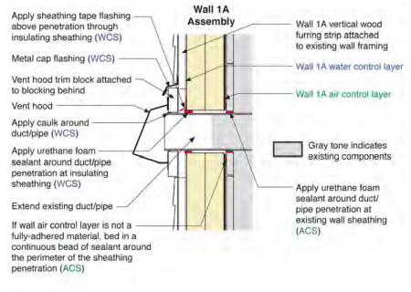
- Duct/Pipe Penetration.
Schematic construction sequences are also provided for some of these assembly interruptions.
This section is divided into two sub-sections to address Wall 1A interruptions and Wall 1B interruptions separately. The difference in location of the water control layer between these two retrofit wall assemblies has important implications for the design and implementation of these details.
Within each sub-section, the interruption featured in this section are grouped into categories:
- Porch and Deck Connections,
- Windows and Doors, and
- Wire and Duct/Pipe Penetrations.
These categories are also indicated on the long edge of the page to aid in navigating through this section.
NOTE THAT DETAILS FOR PORCH ROOF, PORCH CEILING AND DECK CONNECTIONS DO NOT PROVIDE GUIDANCE RELATIVE TO STRUCTURAL SUPPORT. PERSONS IMPLEMENTING THESE DETAILS SHOULD SEEK ADVICE OF A QUALIFIED PROFESSIONAL TO DETERMINE NECESSARY STRUCTURAL SUPPORT AND CONNECTIONS.
Control system component legend
Because of the primary importance of maintaining continuity of the water control and air control at assembly interruptions, the location of the water control layer and air control layer in the retrofit wall assembly is identified for each of the assembly interruption details. Within each assembly interruption detail illustration, the measures or materials critical to maintaining necessary building enclosure control functions are identified using the following key:
WCS Component of water control system
ACS Component of air control system
VCS Component of vapor control system
TCS Component of thermal control system
CCS Component of critter control system
For example:
